使用 Depictor 可视化轴组
对于这个项目,你还需要 CODESYS Depictor 具有有效许可证的附加组件。
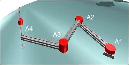
SoftMotion 应用程序由配置为轴组的四个旋转驱动器组成。前三个轴在 X/Y 平面中移动 TCP,第四个轴在 Z 平面中移动。
该示例演示了如何将 Depictor 与 Kin_Scara3_Z 运动学配置结合使用。您还可以为其他运动学配置自定义相同的程序。
创建标准项目
创建一个标准项目 CODESYS SoftMotion Win 控制器和 ST 编程语言。
在中添加库管理器 POU 看法。
打开库管理器并添加库
SM3_Depictor和DepictorBase.
添加和参数化轴
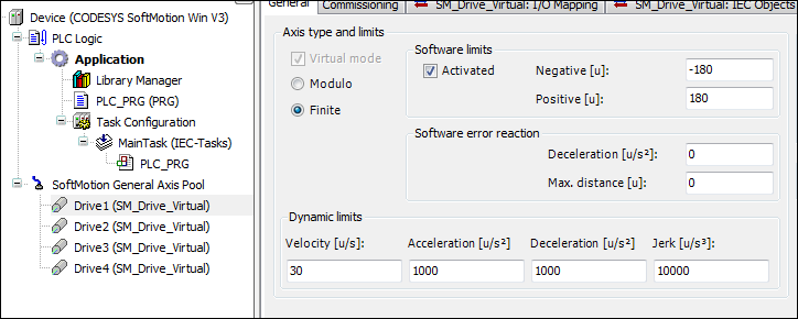
在对象下方插入四个虚拟轴 SoftMotion 通用轴池 并将轴命名为 Drive1...Drive4。
将轴 Drive1、Drive2、Drive3 和 Drive4 参数化为轴类型 有限 软件端从-180度切换到180度。
配置编辑器:
有关更多信息,请参阅: 虚拟驱动器
配置轴组
在应用程序下方添加一个“KinScara”轴组。为此,请单击 .
在配置器中,单击 选择运动学.选择 TRAFO.Kin_Scara3_Z 运动学。
定义参数如下:
d臂长1, d臂长2, d臂长3: 500
偏移量A1, 偏移量A2, 偏移量A3, 偏移量Z: 0
按如下方式对轴进行排序:
A1: 驱动器 1
A2: 驱动器 2
A3: 驱动器 3
Z: 驱动器 4
注意:您可以将轴直接拖到输入字段中。
有关详细信息,请参阅: 运动学
创建控制器程序
在里面
PLC_PRG程序,声明实例MC_Power所有驱动器的功能块。创建一个istate状态图的变量。VAR Power_Drive1, Power_Drive2, Power_Drive3, Power_Drive4 : MC_Power; istate: INT; END_VAR
在实现中定义一个状态图。
CASE istate OF
 0:
 1:
 2:
END_CASE
激活状态下的所有驱动器
0.0: Power_Drive1(Axis:=Drive1, Enable:=TRUE, bRegulatorOn:=TRUE, bDriveStart:=TRUE); Power_Drive2(Axis:=Drive2, Enable:=TRUE, bRegulatorOn:=TRUE, bDriveStart:=TRUE); Power_Drive3(Axis:=Drive3, Enable:=TRUE, bRegulatorOn:=TRUE, bDriveStart:=TRUE); Power_Drive4(Axis:=Drive4, Enable:=TRUE, bRegulatorOn:=TRUE, bDriveStart:=TRUE); IF Power_Drive1.Status AND Power_Drive2.Status AND Power_Drive3.Status AND Power_Drive4.Status THEN istate:=istate+1; END_IF
当轴被激活时,启用轴组(从“停用”切换到“待机”)。
VAR
 GroupEnable:MC_GroupEnable;
END_VAR

1:
 GroupEnable(AxisGroup:=KinScara, Execute:=TRUE);
 IF GroupEnable.Done THEN
  istate:=istate+1;
 END_IF
声明并初始化一个变量以保存机器坐标中的设定值。声明两个类型的实例
SMC_POS_REF以笛卡尔坐标和轴坐标表示 TCP。VAR Frame: MC_COORD_REF:=(X:=-120, Y:=-25); // This variable stores the cartesian position & orientation of the TCP Pos_Cart: SMC_POS_REF; // This variable represents the position of the TCP in cartesian coordinates coordinates Pos_Axis: SMC_POS_REF := (a := axispos);// This variable represents the position of the TCP in Axis coordinates END_VAR VAR CONSTANT axispos: TRAFO.AXISPOS_REF := (a0 := 0, a1 := 100, a2:=60); END_VAR 2: Pos_Cart.c:= Frame; // To represent the TCP in cartesian coordinates;
声明一个实例
MC_MoveDirectAbsolute将 SCARA 机器人移动到指定坐标。VAR MoveAbs:MC_MoveDirectAbsolute; // Moves the TCP to the defined coordinates END_VAR 2: MoveAbs(AxisGroup:=KinScara, Execute:=TRUE, Position:=Pos_Axis,CoordSystem:=SMC_COORD_SYSTEM.ACS, BufferMode:=MC_BUFFER_MODE.Aborting,); //move to the defined Axis coordinates //MoveAbs(AxisGroup:=KinScara, Execute:=TRUE, Position:=Pos_Cart,CoordSystem:=SMC_COORD_SYSTEM.MCS, BufferMode:=MC_BUFFER_MODE.Aborting,); //move to the defined cartesian coordinates IF MoveAbs.Done THEN MoveAbs(AxisGroup:=KinScara, Execute:=FALSE); // Waits for the next new coordinates istate:=2; END_IF声明一个类型的变量
SMC_GroupReadSetPosition以直角坐标和轴坐标读取机器人的当前值。VAR Car_pos, Axis_pos :SMC_GroupReadSetPosition; //to read the current axis values END_VAR 2: Car_pos(AxisGroup:=KinScara, CoordSystem:=SM3_Robotics.SMC_COORD_SYSTEM.MCS, Enable:=TRUE); // to read the current position in cartesian coordinates Axis_pos(AxisGroup:=KinScara, CoordSystem:=SM3_Robotics.SMC_COORD_SYSTEM.ACS, Enable:=TRUE); // to read the current axis values
整个PLC_PRG程序
比较您的程序并添加缺少的程序部分。
宣言
PROGRAM PLC_PRG
VAR
    Power_Drive1, Power_Drive2, Power_Drive3, Power_Drive4 :MC_Power;
    istate: INT;

    GroupEnable:MC_GroupEnable;

    Frame:MC_COORD_REF:=(X:=-120, Y:=-25); // This variable stores the cartesian position & orientation of the TCP
    Pos_Cart:SMC_POS_REF; // This variable represents the position of the TCP in cartesian coordinates coordinates
    Pos_Axis:SMC_POS_REF := (a := axispos);// This variable represents the position of the TCP in Axis coordinates

    MoveAbs:MC_MoveDirectAbsolute; // Moves the TCP to the defined coordinates (PTP)

    Car_pos,Axis_pos :SMC_GroupReadSetPosition; //to read the current position of the TCP in Cartesian and Axis Coordinates and display it on the visu

    scara_Config:trafo.Kin_Scara3_Z_Config; // To set the configuration of the SCARA_3_Z
    kin_Config:SMC_SetKinConfiguration; // To set the defined configuration of SCARA_3_Z to the axis group used
    nPeriod:DINT:=0; // SCARA_3_Z Period
    Xelbow:BOOL:=TRUE;

END_VAR
VAR CONSTANT
    axispos : TRAFO.AXISPOS_REF := (a0 := 0, a1 := 100, a2:=60);
END_VAR
执行
CASE istate OF

0:
 Power_Drive1(Axis:=Drive1, Enable:=TRUE, bRegulatorOn:=TRUE, bDriveStart:=TRUE);
 Power_Drive2(Axis:=Drive2, Enable:=TRUE, bRegulatorOn:=TRUE, bDriveStart:=TRUE);
 Power_Drive3(Axis:=Drive3, Enable:=TRUE, bRegulatorOn:=TRUE, bDriveStart:=TRUE);
 Power_Drive4(Axis:=Drive4, Enable:=TRUE, bRegulatorOn:=TRUE, bDriveStart:=TRUE);

 IF Power_Drive1.Status AND Power_Drive2.Status AND Power_Drive3.Status AND Power_Drive4.Status THEN
  istate:=istate+1;
 END_IF

1:
 GroupEnable(AxisGroup:=KinScara, Execute:=TRUE);

 IF GroupEnable.Done THEN
  istate:=istate+1;
 END_IF

2:
 scara_Config(xElbowRight:=Xelbow, nPeriodA3:=nPeriod);
 kin_Config(AxisGroup:=KinScara,ConfigData:=scara_Config.Config, Execute:=TRUE);
 Pos_Cart.c:=Frame; // To represent the TCP in cartesian coordinates

 Car_pos(AxisGroup:=KinScara, CoordSystem:=SM3_Robotics.SMC_COORD_SYSTEM.MCS, Enable:=TRUE); // read the current position in cartesian coordinates
 Axis_pos(AxisGroup:=KinScara, CoordSystem:=SM3_Robotics.SMC_COORD_SYSTEM.ACS, Enable:=TRUE); // read the current position in Axis coordinates

 MoveAbs(AxisGroup:=KinScara, Execute:=TRUE, Position:=Pos_Axis,CoordSystem:=SMC_COORD_SYSTEM.ACS, BufferMode:=MC_BUFFER_MODE.Aborting,); //move to the defined axis coordinates
 //MoveAbs(AxisGroup:=KinScara, Execute:=TRUE, Position:=Pos_Cart,CoordSystem:=SMC_COORD_SYSTEM.MCS, BufferMode:=MC_BUFFER_MODE.Aborting,); //move to the defined cartesian coordinates

 IF MoveAbs.Done THEN
  MoveAbs(AxisGroup:=KinScara, Execute:=FALSE); // Waits for the next new coordinates
  istate:=2;
 END_IF
END_CASE
创建一个Depictor程序
在应用程序下方添加一个新的“程序”类型的“Depic”POU。为此,请单击 .
声明一个类型的变量
SM3_Depictor.SMC_R_Scara3_Z_Data.声明一个变量LrSize类型LREAL并将变量初始化为 100。VAR ScaraTrafo : SM3_Depictor.SMC_R_Scara3_Z_Data; LrSize:LREAL:=100; END_VAR
在实现中插入对功能块的调用。
ScaraTrafo(AxisGroup:=KinScara, trf:=KinScara.trafo);
将“Depic” POU 添加到 主要任务.
配置描述符
在应用程序下方添加一个“Depictor”对象。为此,请单击 .
双击对象。
选择 姿势 Depictor 树中的元素。
点击 .
这 盒子 元素添加在姿势下方。
选择 插图参考。 元素属性中的选项。
点击
 按钮。
按钮。选择 SMC_R_Depictor_Scara3_Z 从对象
SM3_Depictor图书馆。定义接口变量如下:
脸书: Depic.ScaraTrafo
lrZ_: Drive1.fSetPosition
最小: 10
最大:-50
大小:Depic.LrSize
显示平面: 0
创建可视化
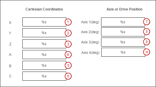
创建一个可视化屏幕,在其中可以显示和修改笛卡尔坐标和轴坐标。
在应用程序下方添加一个“可视化”对象。为此,请单击 .
在编辑器中打开可视化。
插入一个 长方形 可视化元素 (1)。
更改元素的属性。
: %s
:
PLC_PRG.Car_pos.Position.c.X输入类型: VisuDialogs.Numpad
使用另一个变量:
PLC_PRG.Frame.X
插入另一个 盒子 可视化元素。
更改元素 (2) 和 (3) 的属性。
: %s
:
PLC_PRG.Car_pos.Position.c.Y或者PLC_PRG.Car_pos.Position.c.Z输入类型: VisuDialogs.Numpad
使用另一个变量:
PLC_PRG.Frame.Y和PLC_PRG.Frame.Z
更改元素 (4)、(5) 和 (6) 的属性。
: %s
:
PLC_PRG.Frame.A或者PLC_PRG.Frame.B或者PLC_PRG.Frame.C
更改元素 (7)、(8)、(9) 和 (10) 的属性。
: %s
:
PLC_PRG.Axis_pos.Position.a.a0或者PLC_PRG.Axis_pos.Position.a.a1或者PLC_PRG.Axis_pos.Position.a.a2或者PLC_PRG.Axis_pos.Position.a.a3输入类型: VisuDialogs.Numpad
使用另一个变量:
PLC_PRG.Pos_Axis.a.a0和PLC_PRG.Pos_Axis.a.a1和PLC_PRG.Pos_Axis.a.a2和PLC_PRG.Pos_Axis.a.a3
使用以下标签标记可视化元素 标签 元素。
启动和测试程序
您可以在项目的可视化中修改轴值。如果您注释掉活动的移动命令 (MoveAbs..., ...) 在程序中 PLC_PRG 并去掉第二条移动命令的注释,就可以修改笛卡尔坐标了。
构建项目并将其下载到 PLC。
在您的项目中打开 Depictor 对象的编辑器。
切换到可视化并修改轴值或笛卡尔值。在 Depictor 中观察 SCARA 机器人的运动。